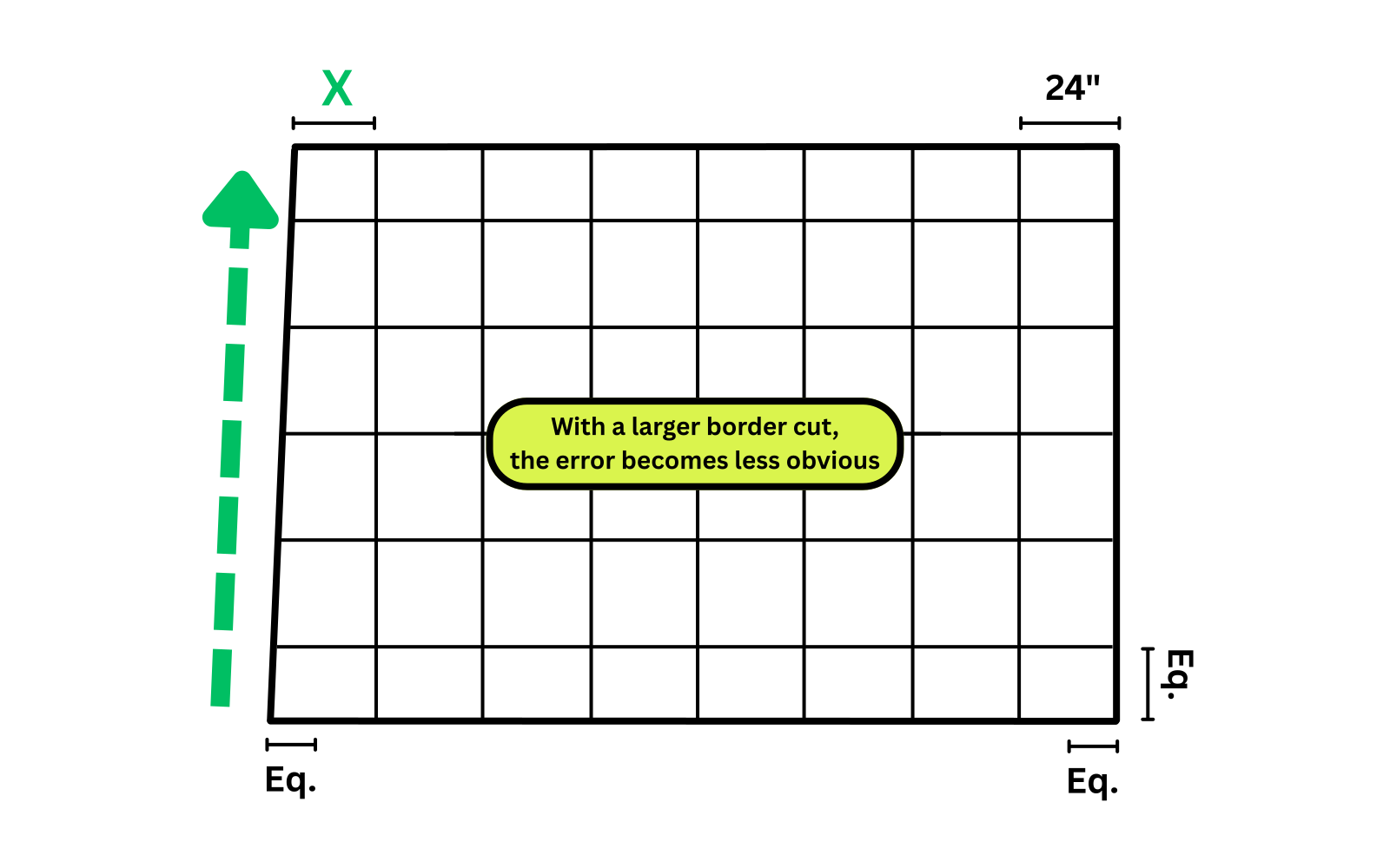
Larger border
BIDSIMP FIELD LESSON
A perfectly centered ceiling is not always the best-looking ceiling in an imperfect room. When walls run out, the job is to understand where the error is, determine how the ceiling will actually be viewed, and choose a straight, coordinated layout that makes the room read as intentionally as possible.
Before changing anything because a wall is crooked, understand what the drawings are asking the ceiling to do. The field condition may be imperfect, but the ceiling can still have a design intent that controls the final decision.
Design intent comes first. An out-of-square room does not automatically mean the ceiling layout can be shifted. If the field condition forces a change, understand the impact before proposing it.
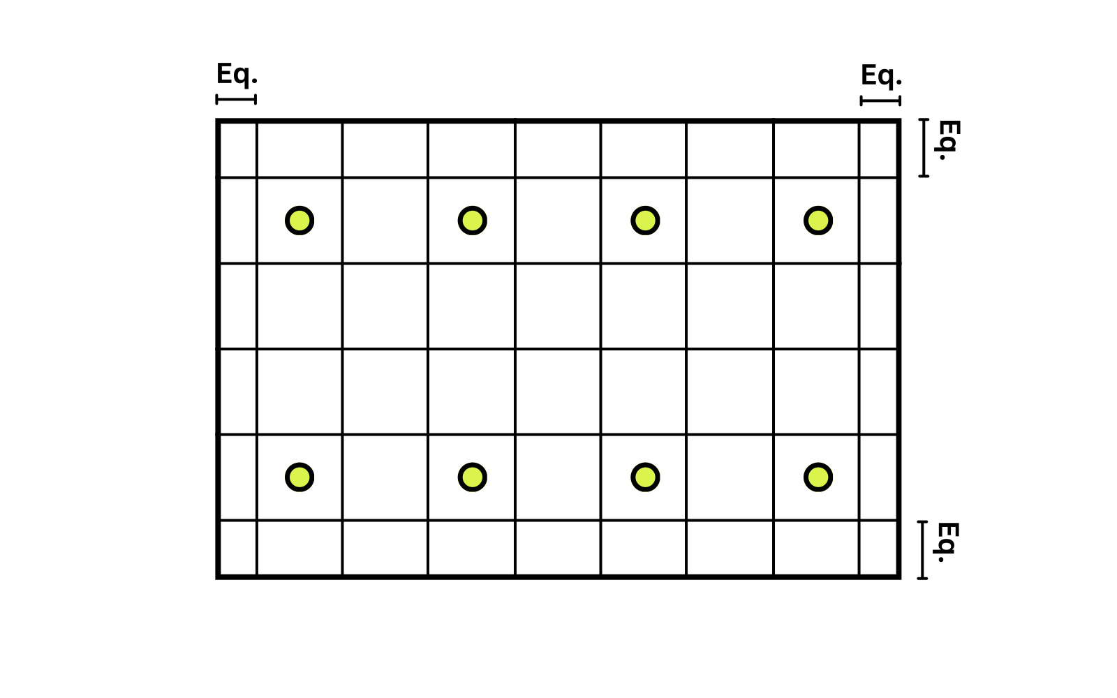
Visual inspection can tell you where to look, but do not rely on your eye alone. Check which walls are square to each other, whether opposite walls stay parallel, and where the room dimension grows or shrinks.
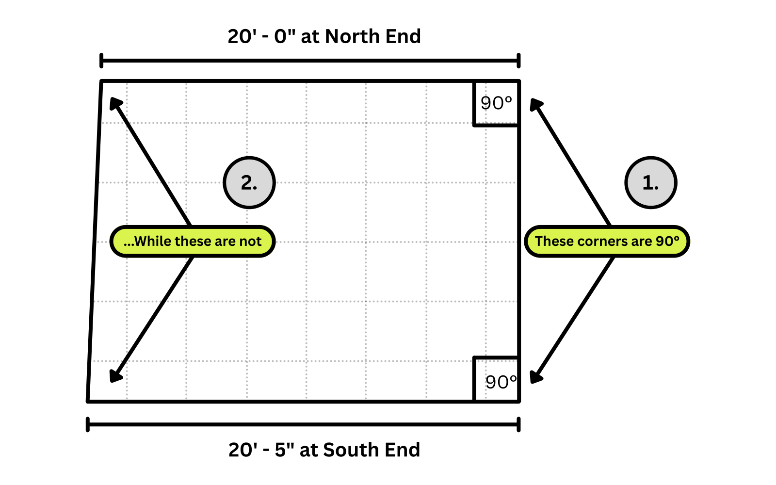
Visual inspection: look down the walls and compare the room shape. A wall that obviously leans or bows is a clue, not a final measurement.
Measure at multiple locations: compare the distance between opposite walls at both ends and, on larger rooms, at intermediate points. This tells you whether the room opens, closes, bows, or jogs.
Laser: a properly set up laser with a 90-degree function can establish square control lines quickly. Follow the laser manufacturer's setup and accuracy requirements.
3-4-5: use a right-triangle check when you need to verify that two lines are 90 degrees to each other.
3-4-5 QUICK CHECK
If one leg is 3 units, the other is 4, and the diagonal is 5, the angle between the two legs is 90 degrees. The same relationship works at any consistent multiple. In the field, use the largest practical triangle you can measure accurately.
| Leg A | Leg B | Diagonal |
|---|---|---|
| 3' | 4' | 5' |
| 6' | 8' | 10' |
| 9' | 12' | 15' |
| 12' | 16' | 20' |
| 15' | 20' | 25' |
Important: a 3-4-5 check tells you whether two lines are square to each other. It does not prove the entire room is square. An opposite wall can still run out, bow, or be out of parallel.
The priority vantage point is the position from which the ceiling will most often be seen or judged. The best layout is not only about the tape measure. It is also about what the room looks like to the people who use it.
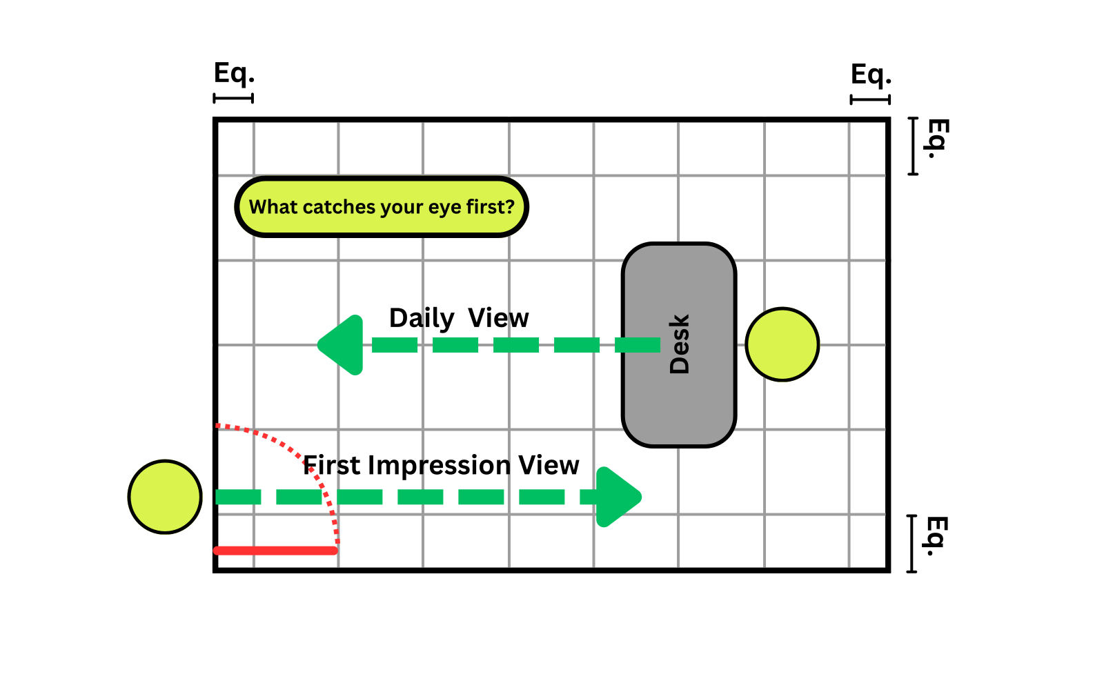
This is a design judgment, not permission to ignore the drawings. Use the priority vantage point to compare acceptable layout options after you understand the project requirements.
Now ask the question that matters: If I hold this layout here, what happens everywhere else? An out-of-square wall makes the perimeter cut grow or shrink as the wall veers away from the square grid.
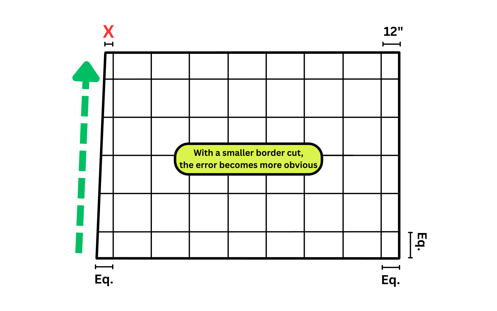
Why small cuts matter: the same wall runout is usually more noticeable when it consumes a large percentage of a small border. A 4-inch change from 16 inches to 12 inches may read far differently than a 4-inch change from 6 inches to 2 inches.
COMPARE THE WHOLE ROOM
Try the layout against all four sides before committing. The goal is to understand the tradeoff, not to force one wall to win automatically.
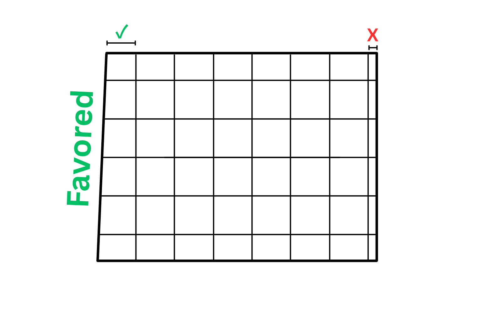
Entry looks excellent, but the opposite corner collapses to a very small cut.
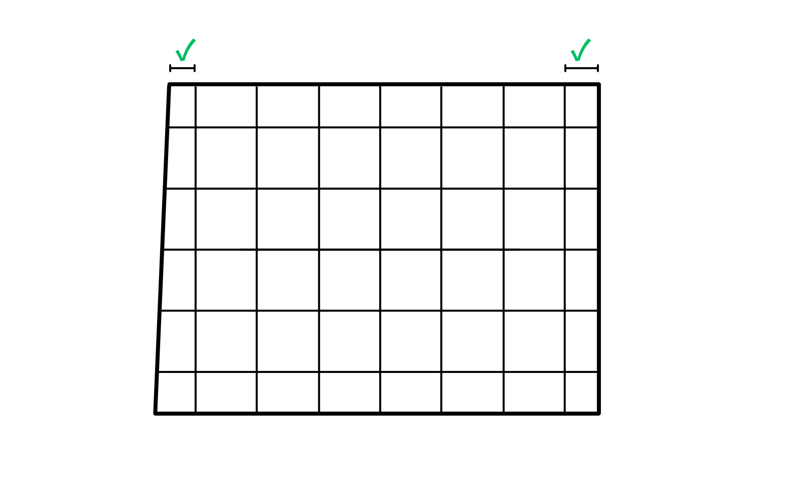
No wall is mathematically perfect, but the room reads more evenly from the main views.
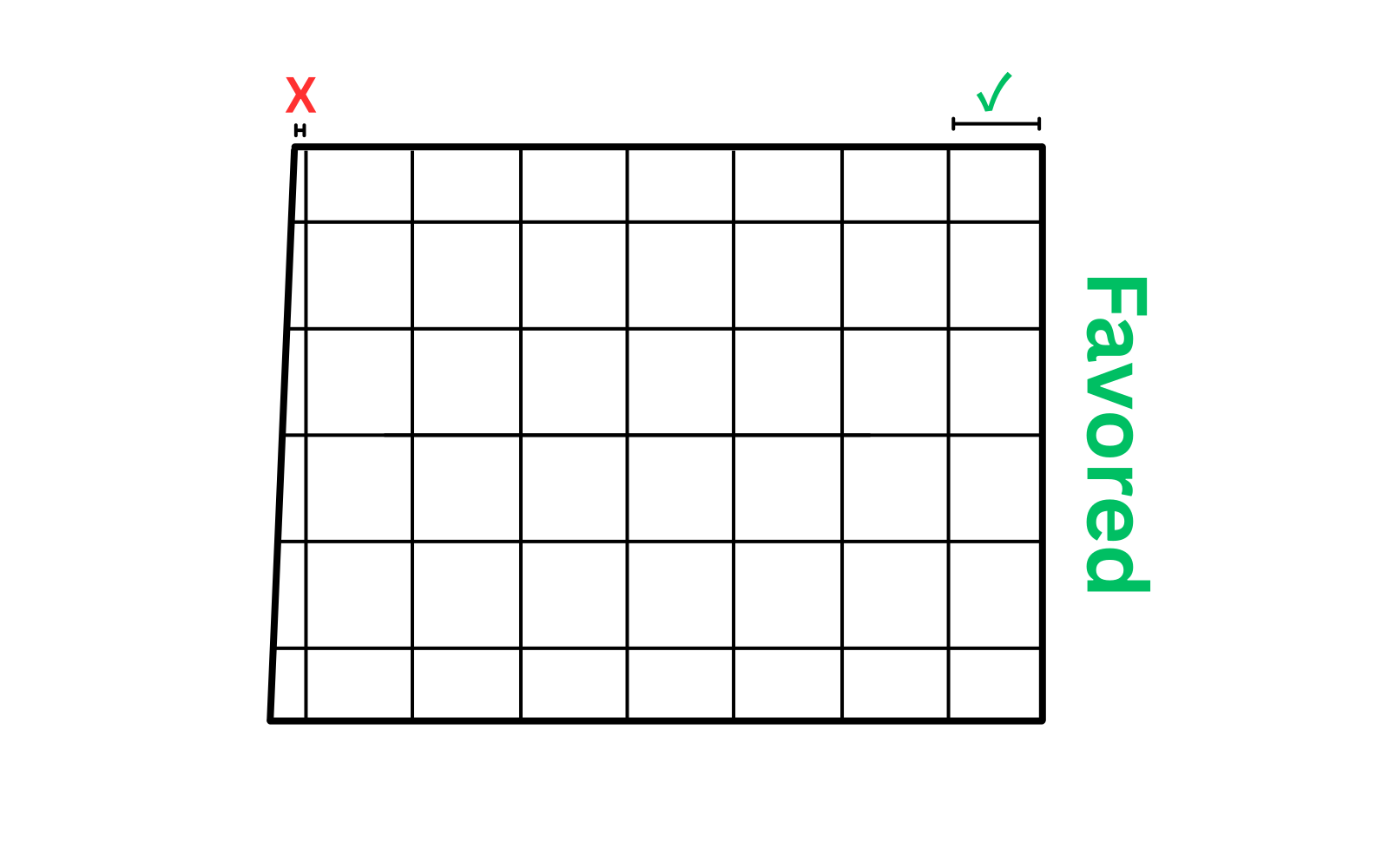
A key feature or corridor aligns cleanly, while a less visible wall absorbs more of the taper.
There is no automatic winner. In this example, Option B may look calmer overall. On another project, the RCP, lighting, a feature wall, or an adjacent space may make A or C the correct choice.
The wall you care about visually and the line you use to square the ceiling are related, but they are not necessarily the same thing.
Priority or reference wall: the wall or view that carries the most visual weight when positioning the grid.
Control line: the straight, square line used to establish the actual grid geometry.
If the priority wall itself is crooked, blindly following it can make the entire ceiling grid crooked. A better approach is usually to establish a straight control line, keep the grid square, and position that square grid so the perimeter condition at the priority wall is as visually acceptable as practical.
Square the grid. Manage the perimeter. Do not intentionally rack an ACT grid to imitate a crooked wall unless the project design specifically requires something different.
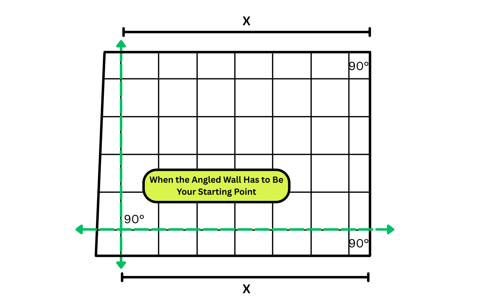
A two-inch shift may improve a perimeter cut, but the ceiling is usually coordinated with more than wall angle. Before recommending a change, look at everything that depends on the module.
Will fixtures stay centered in tiles or aligned with the design?
Does the change affect mechanical or fire-protection coordination?
Will grid lines still align with architectural features?
Does the room need to continue a line from a corridor or neighboring space?
Check speakers, cameras, access panels, and ceiling-mounted equipment.
Verify the RCP, specifications, details, addenda, and approved coordination.
Major field errors should be documented before installation. The best conversation happens after you have measured the condition, understood the impact, and thought through a professional recommendation.
“The north wall runs out about 4-1/2 inches over 28 feet. If we hold the plan layout exactly, the border at the east end drops from roughly 6 inches to about 1-1/2 inches, which makes the wall condition very noticeable from the main entrance.”
“I checked the other walls and the fixture layout. My recommendation is to shift the grid 2 inches so the entrance side stays balanced and the opposite cuts remain reasonable. Here is what that does to the rest of the room. Can we confirm that layout before we install?”
The point is not to sound impressive. The point is to bring a measured condition and a thought-out solution instead of simply reporting that the room is crooked.
QUICK FIELD CHECK
THE BIG IDEA
When the room is imperfect, there may not be a layout that makes every border mathematically equal. The goal is to understand the design, understand the field condition, make the compromises intentionally, and avoid creating an obvious problem in the part of the room people will see most.
Field training aid: This lesson explains a practical process for evaluating out-of-square ACT ceiling conditions. Final layout is controlled by the project drawings, specifications, approved coordination, manufacturer requirements, field measurements, project direction, and applicable requirements. Significant deviations from the design should be documented and approved as required. Terms & Disclaimer